|
 1
2
3
4
5
6
7
8
9

30) Similarly again we have to enter Tabular Values for First Phase as:
- Select S vs Kr as Characteristics.
- Select S Vs Kr as Moisture Characteristics.
- Select First as Fluid Phase Input Specification.
- Select Enter Tabulated relation as Tabular Value.
- Enter 4 as Number of Data Sets.
- Enter the following values as Tabular Values.
| 0.0 |
| 0.0 |
|
| 0.1 |
| 0.0 |
|
| 0.9 |
| 1.0 |
|
| 1.0 |
| 1.0 |
|
- After applying the Tabular Values the Tabulated Values Dialog Will look like as shown in Fig 4.2 below.

Fig - 4.2: Tabulated values with 4 Data Sets
- Click Apply when finished.
31) Similarly Again we have to enter Tabular Values for Second Phase as:
- Select S vs Kr as Characteristics.
- Select S Vs Kr as Moisture Characteristics.
- Select Second as Fluid Phase Input Specification.
- Select Enter Tabulated relation as Tabular Value.
- Enter 4 as Number of Data Sets.
- Enter the following values as Tabular Values 0.0, 0.0, 0.1, 0.0, 0.9, 1.0, 1.0, 1.0.
- After applying the Tabular Values the Tabulated Values Dialog will look like as shown in Fig 4.3 below.

Fig - 4.3: Tabulated data for Second Phase
- Click Apply when finished.
This completes MultiPhase Properties in terms of Tabular Values. Now Close the Multiphase Characteristics Dialog Fig 3.8 and return to Advance Solid Matrix Properties See Fig 3.8a
32) Click on Property Interpretation >> and enter the values as:
- Select Largest of the Two nearest node Values
- From list of Dependent Variables Select P and P2 as shown in Fig 4.4 below.

Fig - 4.4: Property Interpretation for P and P2
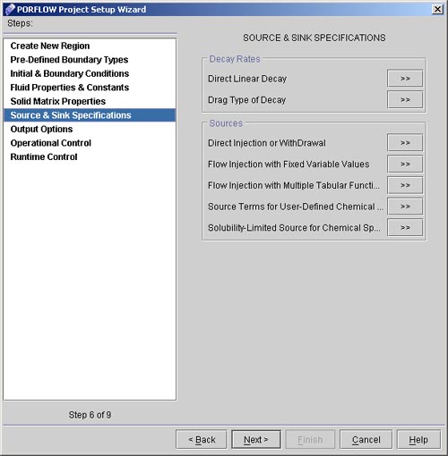
- Click Apply when finished. Select Source and Sink Specifications from Porflow Project Setup Wizard as showing in Fig 4.4a below.

Fig - 4.4a: Source Sink Specification Window
33) Click on Direct Injection Withdrawal >> and enter the Values for Direct Injection as follows:
- Select P as dependent Variable.
- Select Source Strength per element Radio Button.
- Select Strength as Specified Radio Button.
- Select BNDINJ as Region Name from List of Regions.
- From Other Conditions Select Constant and Enter Value 0.01 as shown in Fig 4.5

Fig - 4.5: Source Strength For P
- Click Apply when finished.
34) Similarly Specify P as a Linear function Of S. Click again on Direct Injection Withdrawal and specify the values as:
- Select P as Dependent Variable.
- Select Source Strength per element Radio Button.
- Select Strength as Specified Radio Button.
- Select BNDWDRL as Region Name from List of Regions.
- Select S as Independent Variable.
- Select functional form from Other Conditions and select second option from functional form Dialog to specify Linear function Enter values of 0.0 and -0.01 in the respective text fields of selected option in functional form Dialog See Fig 4.6 below.

Fig - 4.6: Functional Form Dialog
- Click Finish when done with functional form.
- The Direct Injection Dialog will look like as shown in Fig 4.7 below:

Fig - 4.7: Source Strength for P as linear Function of S
35) Similarly Specify Source Strength for P2 as a Linear function of S2. Rest will be same as in previous step only Change dependent Variable to P2 and Independent Variable to S2.
The Direct Injection Dialog in this case will look like as in Fig
4.8.

Fig - 4.8: Source Strength for P2 as a Linear function of S2
This completes the Source and Sink Specification.
 1
2
3
4
5
6
7
8
9

# Back to CFDStudio/PORFLOW Tutorials Page
Related Links:
# PORFLOW Applications
# PORFLOW Express
# PORFLOW Publications
# PORFLOW Users
# PORFLOW Price List
# Request CFDStudio/PORFLOW Demo
# CFDStudio/PORFLOW Tutorials
# PORFLOW Manual
# PORFLOW Validation Report
|


