 |
ACRi -- Analytic & Computational Research, Inc.
|
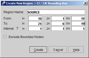
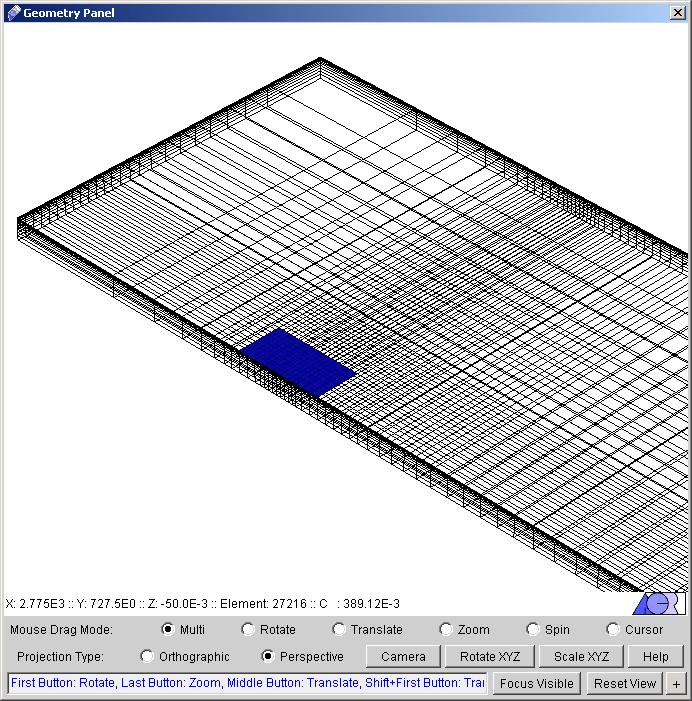
11) Although you can come back to this panel to specify regions at a later stage, it is generally good practice to create any regions that will be used throughout the wizard - i.e., for specifying boundary / initial conditions or field variables, as well as sources - at this stage. We will specify most of the boundary conditions at the entire boundary domain, so we need not create any regions for that purpose. We will create two regions however, one for the SOURCE command, and the other to have output in particular domain. 12) Here we will create a region to represent the source. Click "IJ/IJK Bounding Box >>". A dialog window appears. Enter the values as:
13) The second region will be generated to specify as the problem output region. Click again "IJ/IJK Bounding Box" and enter the values as
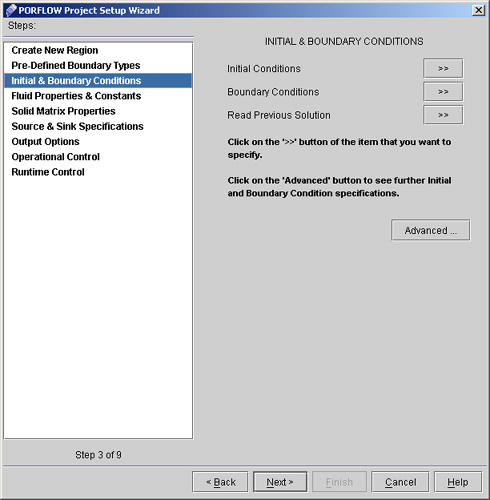
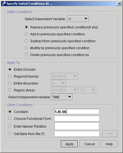
14) Click "Next >" in the wizard dialog to reach the "Pre-defined Boundary types". Here one can define boundary types like inlets, outlets, walls, periodic or symmetry boundaries .The problem we are setting does not have any explicit boundary types to set so we will not work on any of these options. Note that by default all domain boundaries are treated as open boundaries, so we will go with the defaults. 15) Click "Next >" to reach "Initial & Boundary Conditions" (See fig 2.1). We will provide starting values for the problem by setting U as constant value.
16) Click "Initial Conditions >>". A dialog box appears. Set the initial condition for U as follows:
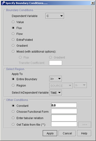
17) Now Click "Boundary Conditions >>" option in order to set the all boundaries as no flow boundaries.
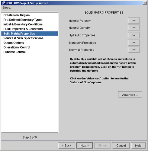
18) We have defined the C flux 0 at X+ boundary. Now Proceed further to specify the boundary condition at remaining five faces. 19) For Y-, Y+, Z- and Z+ we will apply same boundary condition as for X+. So change only entire boundary to Y-, Y+, Z-, Z+ and click Apply every time. 20) For X- everything will remain same as above except the boundary condition type as Value and Entire boundary at X-. Click "Apply". 21) Click "Next" to go to the "Fluid Properties & Constants". For the present problem we will not specify anything from this section. 22) Click "Next >" to reach "Solid Matrix Properties" dialog window as shown on fig 2.4
# Back to CFDStudio/PORFLOW Tutorials Page
Related Links:
# PORFLOW Applications |


