
 |
ACRi -- Analytic & Computational Research, Inc.
|
30) To specify Initial Conditions Select First Dependent VariableU from the list.
31) Click upon Initial Conditions Tab again and enter Dependent variables specifications for P, K and E one by one. Thus Set V=0.0: Change only the dependent variable to V and the constant value to 0.0, click "Apply". 32) Set P=0.0: Change only the dependent variable to P and the constant value to 0.0, click "Apply". 33) Set K=0.01: Change only the dependent variable to K and the constant value to 0.01, click "Apply". 34) Set E=0.111: Change only the dependent variable to E and the constant value to 0.111, click "Apply".
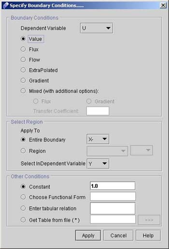
35) Click "Boundary Conditions >>" button. This screen is shown in Fig.2.9. We will provide the experimental inlet values of U and K as a constant value.
36) For U values at the inlet
37) Similarly Set K=0.01: Change only the dependent variable to K and the constant value to 0.01, click Apply".
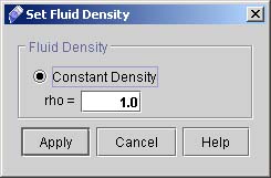
38) Click "Next >" to go to FLUID PROPERTIES & CONSTANTS dialog window. Here we will specify the fluid density and viscosity. 39) Click "Density >>" to go to Set Fluid Density dialog window as shown in fig 3.0
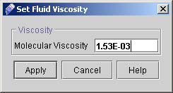
40) Click "Viscosity >>" to go to dialog window for viscosity.
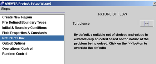
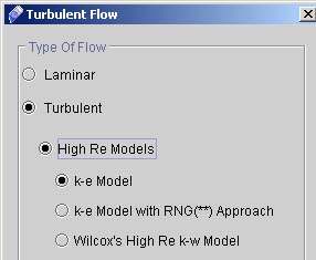
41) Click "Next >" to go to NATURE OF FLOW dialog window (See fig 3.1), and then select the options as follows. Click upon "Turbulence".
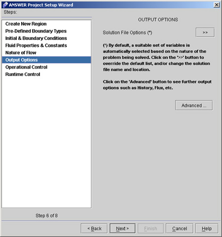
42) Click "Next >" button to go to Output Option dialog window. (see fig 3.3)
# Back to CFDStudio/ANSWER Tutorials Page
Related Links:
# ANSWER Applications |