 |
ACRi -- Analytic & Computational Research, Inc.
|
12) Click on "Apply" button and a dialog window will appear as shown in fig 1.7.
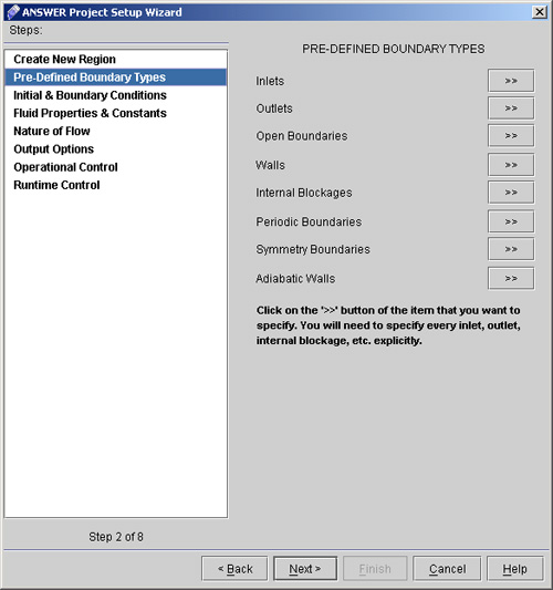
13) Either Click Next or Select the "Pre-Defined Boundary Types" option. (See fig 1.7)
14) Click on "Inlets >>" button on "Pre-Defined Boundary Types" dialog window.
15) Click on "Outlets >>" button on "Pre-Defined Boundary Types" dialog window.
16) Click on "Walls >>".
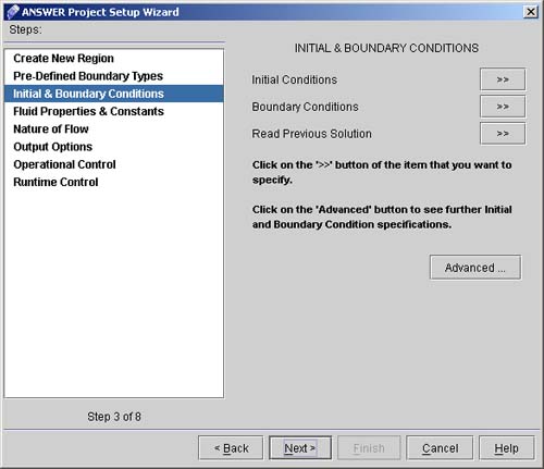
17) Click "Next >" to go to INITIAL & BOUNDARY CONDITIONS screen. (See Fig. 1.8)
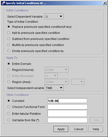
18) Click "Initial conditions >>" to specify the initial guesses for the primary dependent variables. A dialog Window (See Fig. 1.9) will appear where we can set the initial guess for U, V, W, P, K and L.
19) Set U=1.0E-06:
Revisit Initial Conditions Dialog to enter specifications for other Dependent Variables. 20) Set V=1.0E-06: Change only the dependent variable to V and the constant value to 1.0E-06, click "Apply". 21) Set W=1.0E-06: Change only the dependent variable to W and the constant value to 1.0E-06, click "Apply". 22) Set P=1.0E-08: Change only the dependent variable to P and the constant value to 1.0E-08, click "Apply". 23) Set K=0.1: Change only the dependent variable to K and the constant value to 0.1, click "Apply". 24) Set L=0.01: Change only the dependent variable to L and the constant value to 0.01, click "Apply".
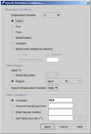
25) Click on "Boundary Condition >>" to specify the boundary condition. The upcoming dialog will be as shown in Fig.2.0.
26) To set U values at the inlet select the options as:
27)Set K=0.1; Change only the Dependent Variable to K and the constant value to 0.1, click "Apply". 28) Set L=0.01: Change only the Dependent Variable to L and the constant value to 0.01, click "Apply".
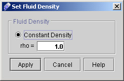
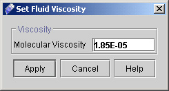
29) Click "Next >" to go to FLUID PROPERTIES & CONSTANTS dialog window.
# Back to CFDStudio/ANSWER Tutorials Page
Related Links:
# ANSWER Applications |


