 |
ACRi -- Analytic & Computational Research, Inc.
|
FLAME TUBE Before You Start: This Tutorial Problem Requires CFDStudio/ANSWER™ v5.5. The users of the software are encouraged to walk through this tutorial and reproduce it on their own while following, rather than just browsing through it. In this tutorial, we will set up a 3D unstructured grid and solve a Turbulent flow using ANSWER™ v5.5. It is advisable that you walk through the first tutorial - the backwards facing step problem - first. Please note that the look and feel of the interface is in constant development, so your screens and dialogs may look substantially different than what you see here. 1) Run ANSWER™ v5.5. The opening screen of ANSWER&trade v5.5 looks like as in Fig.1.1.
2) User is provided with four options
3) In the Title field, type "FlameTube". This is a very important step. The title is used as the folder and file names for all project files. For instance,
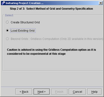
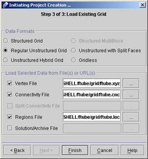
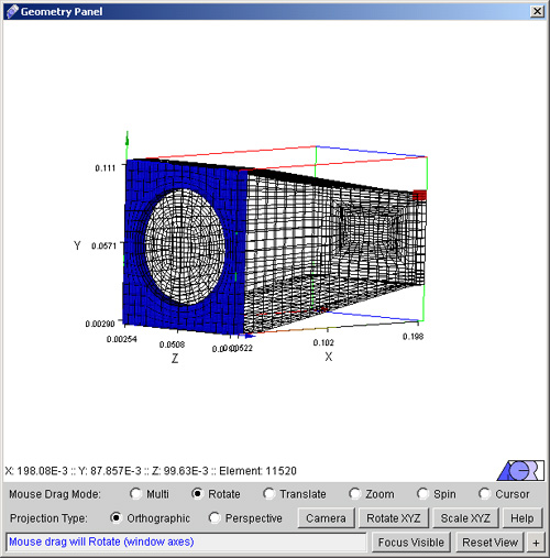
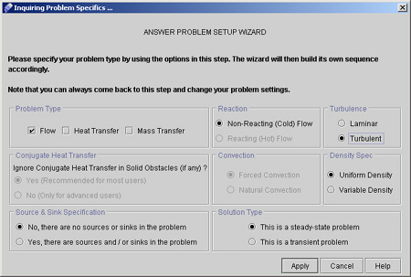
Commands (input) file : FlameTube.inp ... and so on. All these files will be created on the server and placed within a folder also named FlameTube. Hence it is very important that the Project Name is one-word, and not too long. It is a good practice to CapitalizeTheFirstLetterOfEachWord (as opposed to capitalizethefirstletterofeachword) for ease of read. 4) In the User Name field, type your name. Select the 3D, Cartesian options from Project settings 5) For the next step, click "Next>" to reach the Grid and Geometry Specification page (as shown in Fig 1.3) Fig - 1.3: screen for Grid and Geometry Specification 6) Select the option as Load Existing Grid and then click "Next >". We will be reading existing - pre-generated - grid information from the server, for this problem 7) Select the "Regular Unstructured Grid" from data formats (See fig 1.4). To read the files, we have 2 options. We can either read them through the operating system's file browser or we can read them over the web - an intranet or the internet - via http. We will use this latter option since you will be reading the files through ACRi Official Web site. The location of the files is: Fig. 1.4 Dialog box for the loading existing grid "http://acricfd.com/software/answer/tutorials/flametube/grid/"; they are all named "ftube" with the extension ".xyz" for the vertex file, ".cnc" for the connectivity data file, and ".loc" for the regions file. Therefore; 8) Type the following in the text field for Vertex file name: http://acricfd.com/software/answer/tutorials/flametube/grid/ftube.xyz and the same path with the appropriate extensions for the connectivity and regions files. (Hint: Select the path above and copy by CTRL+C, then paste it into the three areas in the Preprocessor dialog by CTRL+V, then change the extensions for the connectivity and regions files appropriately.) ALTERNATIVELY you can download these files in zipped form, extract them to a local directory, and read them locally, as they are pretty big files to download in uncompressed ASCII format. 9) Click "FINISH", and the geometry will appear in the geometry window as shown in Fig.1.5. This operation may take a while depending on your internet connection speed, since the total size of these three files is around 1.5 MB. Therefore it may make more sense to download the zip file and read the files locally. Fig - 1.5: Ftube dataset read from server. 10) From Visualize >> Select Region on menu bar we can select different regions to see their locations on the screen. Take some time now to play around with the geometry by making use of the advanced features of the visualizer such as rotating, zooming in and translating. The small red cube on the grid is the Cursor 11) Choose the options on "Answer Problem Setup Wizard" depending upon our problem requirements as shown in fig. 1.6. Fig.1.6 Answer Problem Setup Wizard. # Back to CFDStudio/ANSWER Tutorials Page Related Links:
# ANSWER Applications |


