|
 1
2
3
4
5
6
7
8
9
1
2
3
4
5
6
7
8
9

TWO PHASE FLOW
Oil - Water Displacement
Before You Start: This Tutorial Problem Requires PORFLOW™. The users are encouraged to walk through this tutorial and reproduce it on their own while following, rather than just browsing through it.
In this tutorial, we will be setting up a 3D unstructured hybrid grid and solving the two phase problem using PORFLOW™ in series of Steps.
1) Launch PORFLOW™. The opening screen of PORFLOW™ looks like as shown in Fig. 1.1.
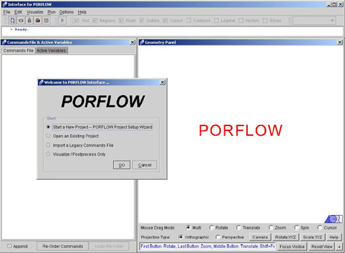
Fig - 1.1: Opening screen for PORFLOW™
This is basically frame window with menu bar, tool bar and status bar at the top followed by command window in the left and geometry window in the right. The top bar provides the navigational menus, and has the look & feel of a generic windows menu bar. The left frame is the home of the command file and a list of active variables for the problem at hand. Finally, the right frame hosts the ACRi Geometry Panel. A dialog also appears on the main browser window stating various options.
We can start setting up the problem now, using PORFLOW™.
2) Click "Start a New Project- PORFLOW Project Setup Wizard" >> Go, to start the project. A new dialog window appears to specify the project identification having options like project title, User name and the options for the grid type. Enter the required information as shown in Fig. 1.2. Note that the "User Name" section is filled out automatically with your
username as is registered on your computer.
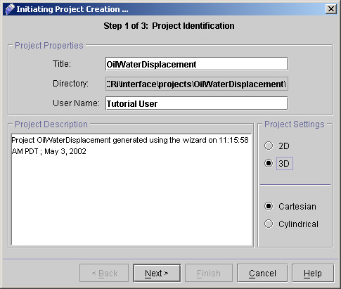
Fig - 1.2: Project Identification dialog box
3) In the Title field, type "OilWaterDisplacement". This is a very important step. The title is used as the folder and file names for all project files. For instance,
Commands (input) file: OilWaterDisplacement.inp
Output file: OilWaterDisplacement.out
Archive (save) file: OilWaterDisplacement.sav
Diagnostics file: OilWaterDisplacement.dgn
... and so on. All these files will be created on the server and placed within a folder also named OilWaterDisplacement. This folder will be saved in the path as shown in the Directory Field in the Fig.1.2. Hence it is very important that the Title of the project is one-word, and not too long. It is a good practice
to CapitalizeTheFirstLetterOfEachWord (as opposed to capitalizethefirstletterofeachword) for ease to read.
4) In the User Name field, type your name and For specifying the grid type, select either 2D or 3D based upon your Project requirements. Here in this case we will choose 3D Cartesian. Project Description area provide you the current details of Project including Project Title, Date and time.
5) Click Next >> to go to Grid and Geometry Specifications as shown in Fig 1.3.
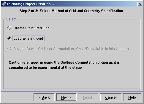
Fig - 1.3: Screen for Grid and Geometry Specification
6) Select Load Existing Grid and Click "Next>>".
7) You will get Load Existing Grid Dialog. Here you have to specify the Vertex and Connectivity Files for your Unstructured Hybrid Grid.
8) Select Unstructured Hybrid Grid. You will get the following Screen (Fig 1.4).
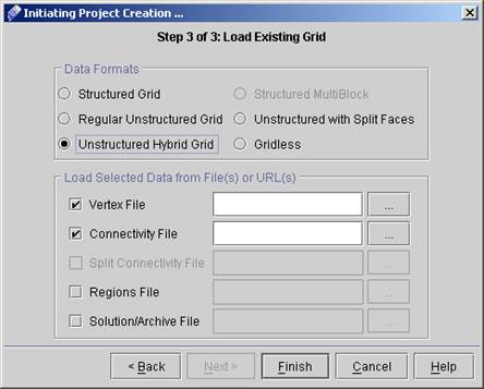
Fig - 1.4: screen for Load Existing Grid.
Now specify Vertex and Connectivity files. The files that we are going to use are Porh01.xyz and Porh01.cnc. These files can be downloaded easily from this link, in zipped format (~56kB or 3-4 seconds w/ 28.8kbps). Extract them anywhere in your local disk and browse to them using the "..." browse buttons.
Click Button next to Vertex file text Field to select the vertex file (PORH01.XYZ). During browsing the following screen will appear (Fig 1.5).
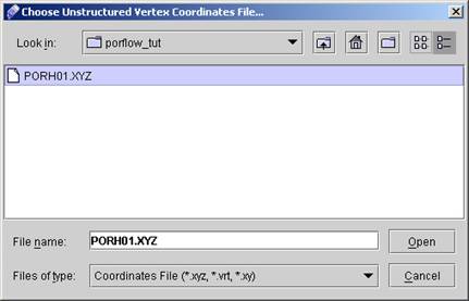
Fig - 1.5: Screen for Browsing Connectivity File.
In the Look in: Box Select the name of Folder where you have stored the required vertex File (PORH01.XYZ).
Select the file and click Open. Similarly Browse for Connectivity file. After successfully locating both the files the final Dialog window for Load Existing Grid will be as shown in Fig 1.6.
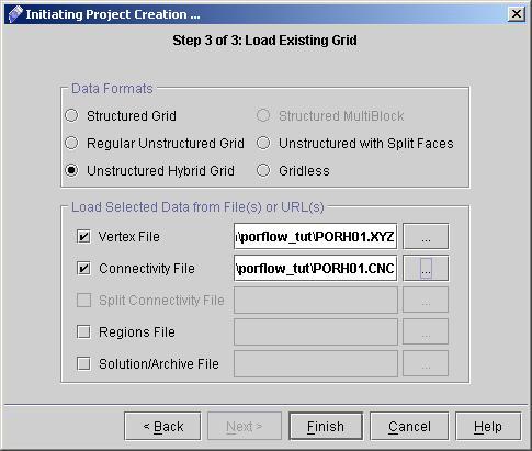
Fig - 1.6: Load Existing Grid Dialog After browsing the files
1
2
3
4
5
6
7
8
9
# Back to CFDStudio/PORFLOW Tutorials Page
Related Links:
# PORFLOW Applications
# PORFLOW Express
# PORFLOW Publications
# PORFLOW Users
# PORFLOW Price List
# Request CFDStudio/PORFLOW Demo
# CFDStudio/PORFLOW Tutorials
# PORFLOW Manual
# PORFLOW Validation Report
|