
 |
ACRi -- Analytic & Computational Research, Inc.
|
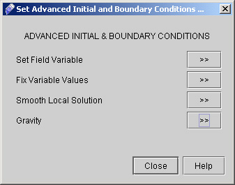
18) We have defined the P flux 0 at X- boundary. Now Proceed further to specify the boundary condition at remaining three faces. 19) For X+, Y+ we will apply same boundary condition as for X-. So change only entire boundary to X+ and Y+ and click Apply every time. 20) For Y- everything will remain same as above except the boundary condition type as Value and Entire boundary at Y-. Click "Apply". 21) Click "Advanced.." on Initial & Boundary Conditions dialog window to reach Advanced Initial & Boundary Conditions dialog window (see Fig 2.5)
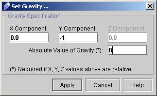
22) Click "Gravity >>". A dialog window appears. Here we will specify the normalized value of gravity. Enter the value as shown in fig 2.6 and click "Apply".
23) Close the Advanced Initial & Boundary Conditions dialog box by clicking on "Close".
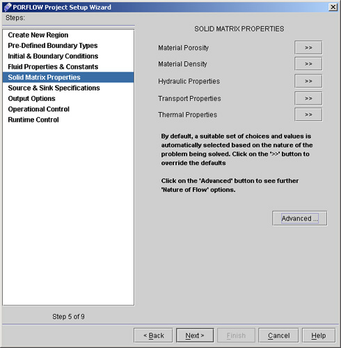
24) Click "Next" to go to the "Fluid Properties & Constants". For the present problem we will not specify anything from this section. 25) Click "Next >" to reach "Solid Matrix Properties" dialog window as shown on fig 2.7
26) Select "Hydraulic Properties >>" from Solid Matrix Properties dialog window and enter the values as follows
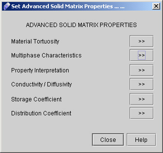
27) Now go to "Advanced" button available on Solid Matrix Properties dialog window. (See fig 2.8)
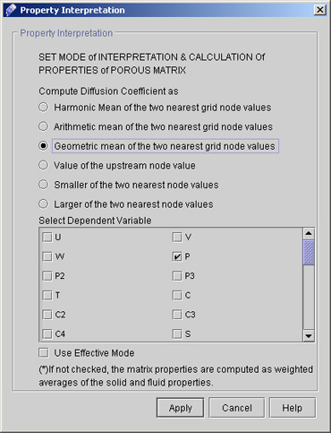
28) Select "Property Interpretation >>". A dialog window appears. Choose the option as:
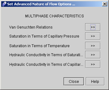
29) Now go to "Multiphase Characteristics >>" option. A dialog window appears as shown in fig 3.0
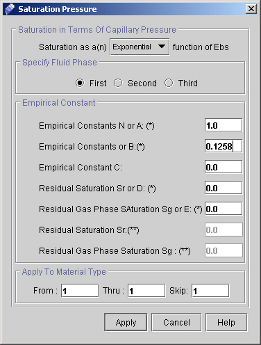
30) Click "Saturation in terms of Capillary Pressure >>" and enter the value as:
# Back to CFDStudio/PORFLOW Tutorials Page
Related Links:
# PORFLOW Applications |