HOME
SOFTWARE
--- CFDStudio
--- ANSWER
--- PORFLOW
Applications
Examples
PORFLOW Express
Publications
Users
Price List
Request Demo
PORFLOW Tutorials
PORFLOW Manual
Validation Report
--- TIDAL
--- RADM
--- TOOLS
DOWNLOADS
APPLICATIONS
CONSULTING
STORE
COMPANY
CONTACT
FAQ
 

ACRi -- Analytic & Computational Research, Inc.


1 2 3 4 5 6

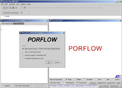
INFILTRATION FROM A LINE SOURCE TO A WATER TABLE

Before You Start: This Tutorial Problem Requires PORFLOW™. The users are encouraged to walk through this tutorial and reproduce it on their own while following, rather than just browsing through it.

In this tutorial we will describe the flow from a single subsurface irrigation pipe that is placed above a shallow water table. Here the our objective will be to determine the resulting steady state flow distribution from the pipe into the surrounding soil.

In this tutorial, we will be setting up a 2D structured grid and solving the problem using PORFLOW™.

1) Run the Interface as PORFLOW™ as the Application. The opening screen of PORFLOW™ looks like as in Fig.1.1.

Fig - 1.1: Opening screen for PORFLOW™

This is basically frame window with menu bar, tool bar and status bar at the top followed by command window in the left and geometry window in the right. The top bar provides the navigational menus, and has the look & feel of a generic windows menu bar. The left frame is the home of the command file and a list of active variables for the problem at hand. Finally, the right frame hosts the ACRi Geometry Window. A dialogue also appears on the main browser window stating various options.

We will proceed step by step to set up the problem, using PORFLOW™

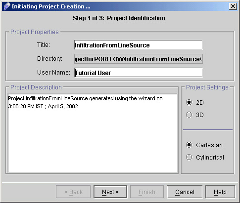
2) Click "Start a New Project - PORFLOW Project Setup Wizard" >> Go, to start the project. A new dialog window appears to specify the project identification having options like project title, User name and the options for the grid type. Enter the required information as shown in Fig. 1.2. Note that the "User Name" section is filled out automatically with your username as is registered on your computer.

Fig - 1.2: Project Identification dialog box

3) In the Title field, type "InfiltrationFromLineSource". This is a very important step. The title is used as the folder and file names for all project files. For instance,

Commands (input) file: InfiltrationFromLineSource.inp
Output file: InfiltrationFromLineSource.out
Archive (save) file: InfiltrationFromLineSource.sav

... and so on. All these files will be created and placed within a folder also named InfiltrationFromLineSource.

Hence it is important that the Title of the project is one-word, and not too long. It is a good practice to CapitalizeTheFirstLetterOfEachWord (as opposed to capitalizethefirstletterofeachword) for ease of read.

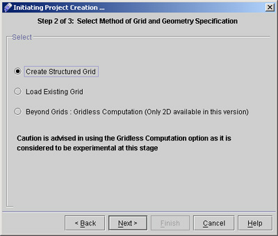
4) In the User Name field, type your name and For specifying the grid type, select either 2D or 3D based upon your Project requirements. Here in this case we will choose 2D Cartesian. Project Description area provide you the current details of Project including Project Title, Date and time.

5) For the next step, click Next> to reach the Grid and Geometry Specification page (as shown in Fig 1.3)

Fig.1.3: screen for Grid and Geometry Specification

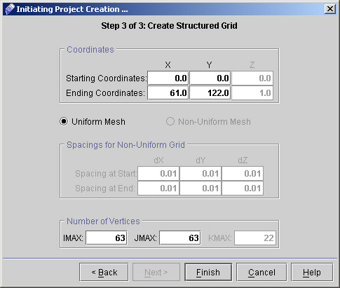
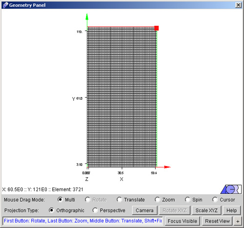
6) Select "Create Structured grid" and then click "Next >".

7) We will generate a 2-Dimensional geometry according to our problem requirements. In the present problem lateral extent of the computational domain is 61 cm and the depth is 122 cm. So proceed according to following steps-

  1. Specify starting coordinates X,Y (0.0,0.0) and ending coordinates X,Y (61.0,122.0).
  2. Select uniform mesh option and specify 63 vertices (IMAX) in X-direction, 63 vertices (JMAX) in Y-direction in order to specify 1 cm grid spacing in X-direction and 2 cm grid spacing in Y-direction. (see fig 1.4 with filled values)

Fig - 1.4: Cretae Structured Grid dialog box

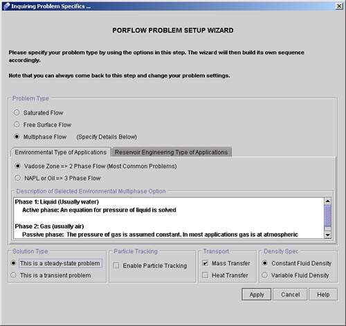
8) Click on "Finish" button. Defined geometry will be created in the geometry panel and a dialog window will appear as "PORFLOW PROBLEM SETUP WIZARD". (See Fig.1.5 and 1.6)

Fig - 1.5: Geometry panel after creating the grid

We can choose various options like Rotate, Zoom, Spin etc. from Mouse Drag mode on Geometry panel. Try to play with these options to get feel of the geometry.

Fig - 1.6: Dialog for PORFLOW Problem Setup Wizard.

9) We will choose different options from "PORFLOW Problem Setup Wizard" dialog depending upon the requirements of our problem (see fig 1.6)

  1. Select Problem type as "Multiphase Flow".
  2. Click the tab "Environmental Type of Applications" and choose option Vadose Zone ==> 2 Phase Flow. You can see the description of selected environmental multiphase option from the text area below.
  3. Solution type as "This is a steady-state problem".
  4. Density Spec as "Constant Fluid Density".
  5. Leave "Enable Particle Tracking" unchecked for the present problem.
  6. Under transport option check "Mass Transfer".
  7. Click "Apply".

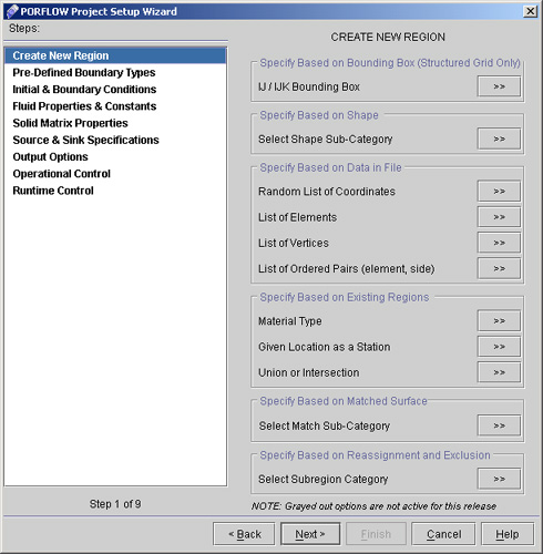
10) A "PORFLOW Project Setup Wizard" dialog window appears as shown in fig 1.7. This will guide us to set up the problem step by step.

Fig - 1.7: Window for PORFLOW problem setup Wizard

1 2 3 4 5 6


Back to CFDStudio/PORFLOW Tutorials Page


Related Links:

PORFLOW Applications
PORFLOW Express
PORFLOW Publications
PORFLOW Users
PORFLOW Price List
Request CFDStudio/PORFLOW Demo
CFDStudio/PORFLOW Tutorials
PORFLOW Manual
PORFLOW Validation Report


HOME | SOFTWARE | DOWNLOADS | APPLICATIONS | CONSULTING | STORE | COMPANY

© 2015 ACRi