
 |
ACRi -- Analytic & Computational Research, Inc.
|
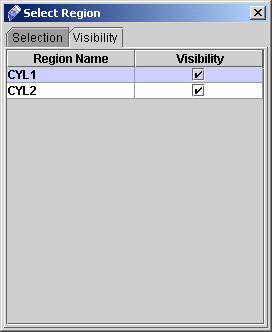
19) A dialog window will appear, Click on "Visibility" and then click on the box provided (see Fig 2.3). Close the dialog box by clicking on cross.
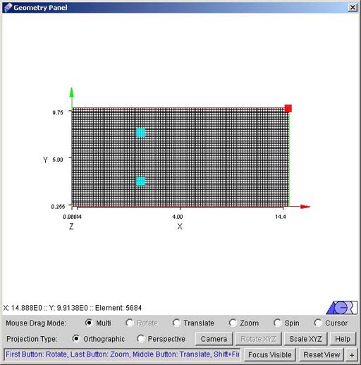
20) Click "Close" and on geometry panel flow domain will appear with all regions (See Fig 2.4)
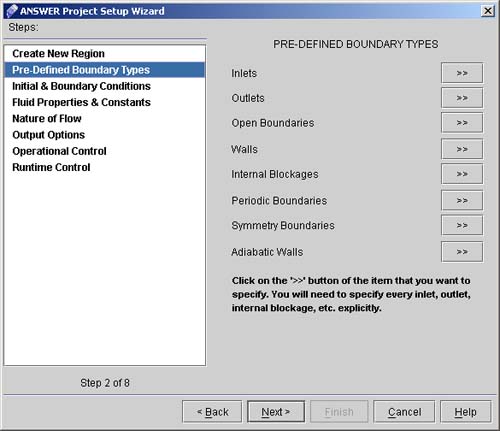
21) Click "Next >>" on Fig 1.7 to go to "Pre-defined Boundary Types" dialog window (see Fig 2.5)
22) Click "Inlets >>" button on "Pre-Defined Boundary Types" dialog window.
23) Click "Outlets >>" button on "Pre-Defined Boundary Types" dialog window.
24) Click on "Walls >>" button on "Pre-Defined Boundary Types" dialog window.
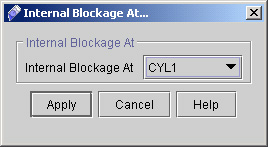
25) Click "Internal Blockage >>" button and select the region as CYL1 and click "Apply". (See fig 2.6)
26) Repeat the step 21 to select the CYL2 as Internal Blockage. Click upon "Apply". A Dialog box "Add or Replace" will pop-up. Since we have to add a different command so we need to choose option "Add as a New Command". Click upon OK Button.
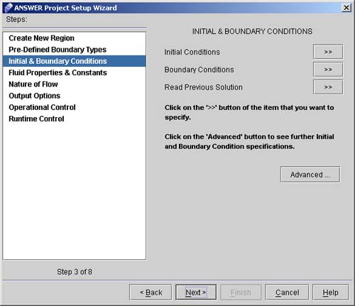
27) Click "Next >"to go to INITIAL & BOUNDARY CONDITIONS dialog window. (See Fig. 2.7)
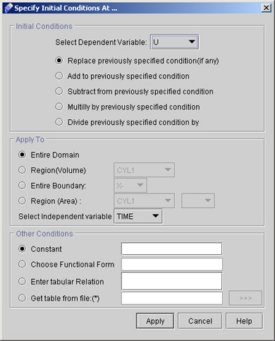
28) Click "Initial Conditions >>" button to specify the initial guesses for the primary dependent variables. 29) The corresponding screen looks like Fig.2.8. We will set the initial conditions for axial velocity U, vertical velocity V, pressure P, turbulence kinetic energy K, and dissipation rate of turbulence kinetic energy E.
# Back to CFDStudio/ANSWER Tutorials Page
Related Links:
# ANSWER Applications |